03UWASIC · Oct 2026

SPI-Controlled PWM Peripheral

3/3cocotb tests passing

Layout render
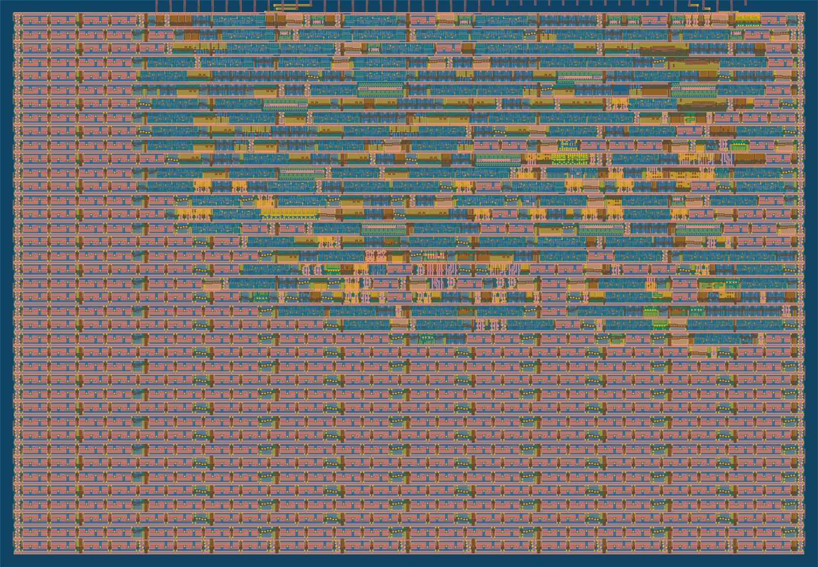
A GDS layout render of the design, a rectangle made of dozens of horizontal rows of small cells. The upper half is densely packed; the lower half is rows of repeating, near-identical cells.
A render of the design's layout (GDS), generated by the project template's automated build. It contains my SPI peripheral and the team's PWM module. The design was taped out.

Simulation output

A simulation waveform of one SPI write, with eight signals. ncs falls at the start, sclk gives 16 pulses while copi carries the command's bits, bit_count counts them, and shift_reg fills to 80f0. Then ncs rises, and en_reg_out_7_0 and uo_out change to f0.
  1. ncs goes low
  2. 16 clock pulses
  3. shift_reg fills to 80f0
  4. The register updates to f0
My simulation waveform of one SPI write. ncs goes low, 16 clock pulses shift a 16-bit command in (shift_reg reaches 80f0), then ncs goes high and the register output and uo_out change to f0.

Illustration

SPI mode 0 timing: ncs, the active-low chip select, is low for 16 sclk pulses; one bit of the command is on copi per pulse, read on each rising edge. The command then sets one of five registers, which control 16 PWM outputs.ncsactive-lowsclkcopiread on each rising edgeone 16-bit commandRegistersPWM16 outputs (the team's PWM module)

Nothing sent yet. A command takes 16 clock pulses.

The shape of the protocol: SPI mode 0, one 16-bit command, five registers, 16 outputs. The signal names are the design's. It is not output from my simulation, and it shows no real register names or values.

What I did

This was my onboarding project at UWASIC, Waterloo's student ASIC design team.

I wrote a mode-0 SPI peripheral in basic Verilog RTL. It receives 16-bit commands and sets five registers that control the team's 16-output PWM module. The PWM module was provided; I wrote the SPI peripheral.

I handled clock-domain crossing with two-flip-flop synchronizers into the 10 MHz clock domain.

The design was taped out.

How I verified it

I verified the design in simulation, writing the cocotb tests for PWM frequency and duty cycle. All three tests pass.

Tools

  • Verilog RTL (basic)
  • cocotb testbenches, Python

Source on GitHub: SPI-Controlled PWM Peripheral
